As the name suggests, fixed joint fixes or locks two parts so that they cannot move or rotate with respect to each other. It has zero degrees of freedom for the rotation and the translation. It gives similar results as bonded contact situations. For a fixed joint, the location and orientation of the joint often do not affect the outcome of the simulation.
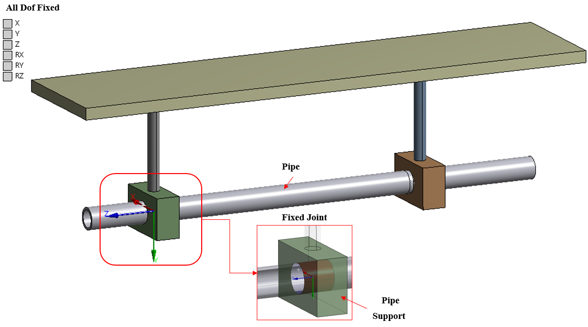
Figure 1 shows the horizontal pipe supported by two square blocks. Here the fixed joint is defined between the pipe and its support, which replicates that the pipe will not rotate or translate into its support.

Figure 1: Fixed Joint
Fixed Joint Details:
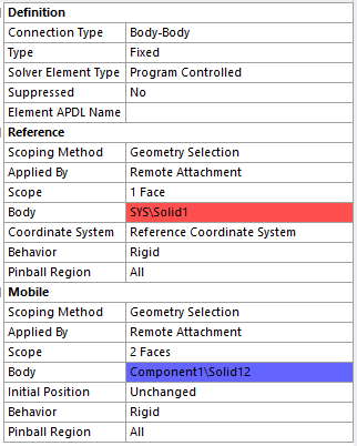
The joint is define either between two body or else between body & ground. Figure 2 shows the joint definition in ANSYS software. Here, you first need to select the connection type such as body to body and then select pipe in reference scope and square block in mobile scope. It can select the coordinate system by default and even you can rotate to define the references as per requirement. Furthermore, you can select behavior as rigid, deformable or beam, which connects two bodies though rigid (elements links) or deformable links or beams.

Figure 2: Fixed Joint Definition Details
Summary:
- Fixed joint is type of joint with zero degree of freedom.
- Fixed joint is used to connect the two body having no relative motion between them.
- For a fixed joint, the location and orientation of the joint often do not affect the outcome of the simulation
